This project builds upon the flashing LED of the first project. If you were motivated, you could change the frequency of the flashing, by adjusting a constant in the program, a “delay” value that was used to turn on and off the power to the LED.
This circuit instead brings in the concept of analog versus digital circuits, something that is worth explaining.
In the digital realm, a signal is “on” or “off”. It is “binary” in that there are solely two states, represented by the values “0” and “1”. An awful lot of the modern world can be reduced to such simplicity.
However, we live in an analog world, where instead of “on” or “off” there is a graduated scale from 0 to a value (let’s assume that our value ranges are from 0V to 5V), in this case 5 volts.
So , instead of an on/off scenario, something that can be represented with a binary digit (or bit), you have a range. How would you represent it? As a number, a value from 0 to some number of increments. Each value is read, and converted to a digital value, and then represented by a number. For the analog inputs on the Arduino, the ADC (or analog to digital conversion) has the resolution of 10 bits (that is 210, or 1024). Thus values can be represented by the integers 0, 1, 2, … 1023, for a total of 1024 unique values.
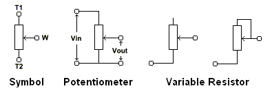 This circuit is pretty simple. It adds a potentiometer that is a continuously variable resistor, that has three connections, the ground, the maximum voltage (note: not necessarily limited to 5 volts, but 5v in our TTL), and the variable output. We connect this variable output to the analog input on the arduino.
Note: the analog pins on the arduino are all input reading pins. There is (as far as I can tell) no DAC (digital to analog converter) available on the board. To do a variable output, you need to resort to PWM, something really cool that will be part of the third project
 Like with the first project, this uses a pretty simple circuit, were we add in a circuit to “read” the voltage that comes off the potentiometer, and to use that to change the delay value of the flash algorithm in the main program loop.
Not too exciting, but you get to play with both inputs and outputs in this circuit, and have more opportunities to screw it up, so some troubleshooting becomes important.